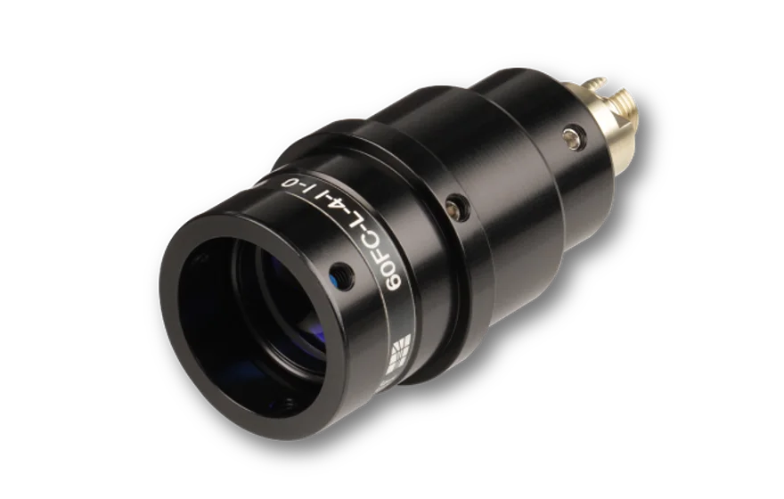
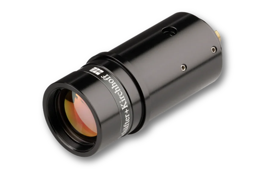
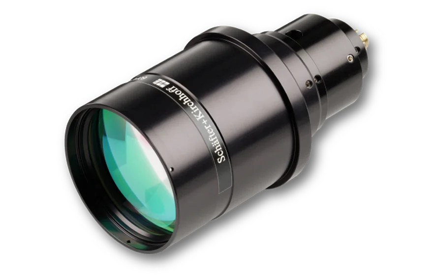
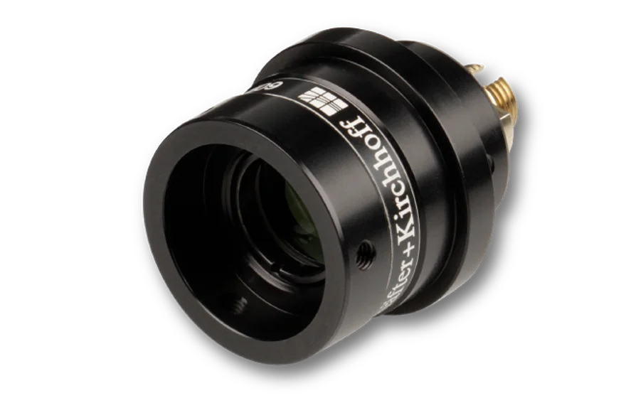
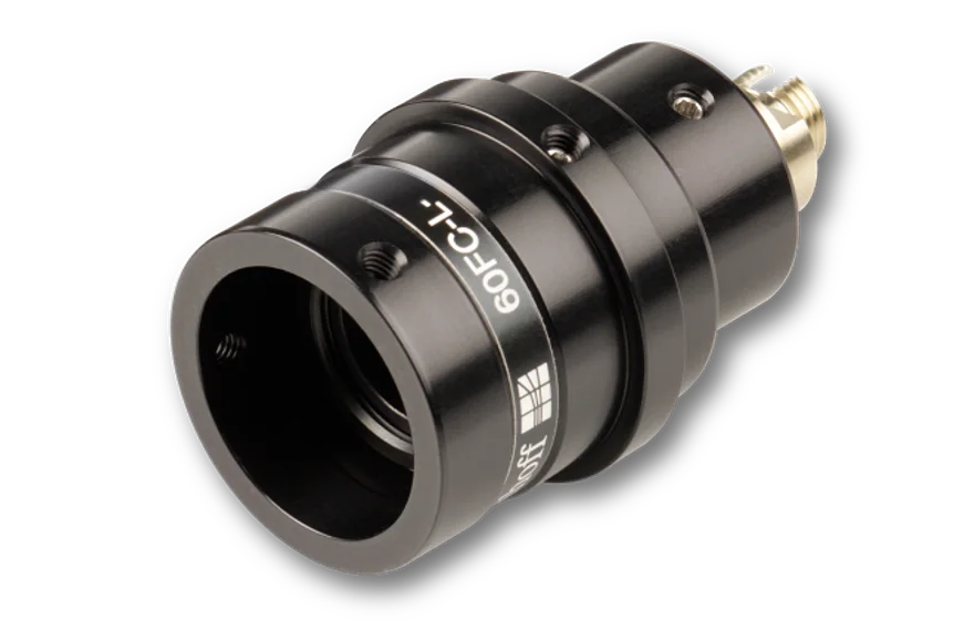
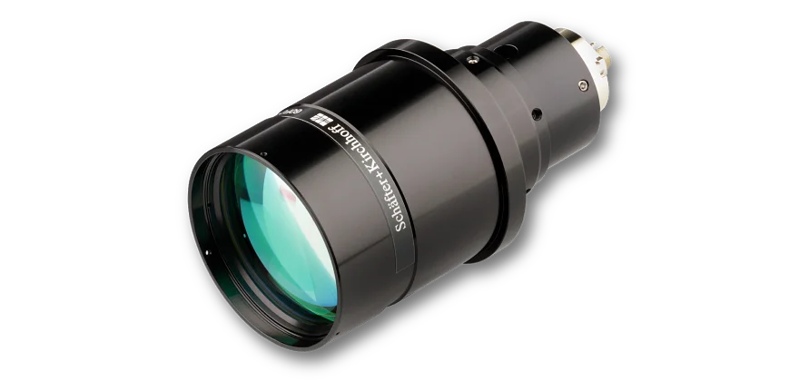
The fiber collimators series 60FC-L are designed for collimating radiation exiting optical fiber cables with high pointing stability and large beam diameters. They can also be used in reverse-mode as fiber incouplers. They are suitable for single-mode and polarization-maintaining fiber cables leading to collimated beams with a Gaussian intensity profile. Please note that for multimode collimation the intensity profile is not Gaussian and depends on specific fiber and radiation properties.
An optics for each applicationA large variety of collimating optics allows that the optimum focal length and the best lens type for a single wavelength (
monochromat) or a wavelength range (
achromat or
apochromat) can be selected for each application. All lenses are AR-coated. The optics' NA is defined by the clear aperture and should be at least twice the
1/e2 effective fiber NA in order to prevent aberrations (e.g. clippling and diffraction). In case of multimode fibers, the optics' NA simply needs to be larger than the fiber NA.
Adjustment of focusThe mechanism to adjust the focus depends on the collimator housing. For collimators with diameter Ø 25 mm the distance between fiber end-face and collimating optics is adjusted by manually shifting the lens tube. For collimators with diameter Ø 32 or larger the distance between fiber end-face and collimating optics is adjusted by means of an eccentric key. The lens does not rotate when adjusting the focus fo both cases. The final focus setting is locked by means of two radially arranged clamping screws. Additionally attachment optics can be mounted to the front of the collimator.
Optimum lens performance The angled polish of connectors of type APC is considered by a
pre-angled mechanical coupling axis that compensates the beam deflection and you can use the lens centrically. This minimizes aberrations simply resulting from a non-ideal beam path through the lens.
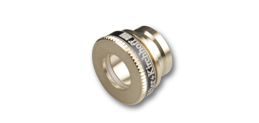
Connector Type The fiber collimator can be equipped with FC PC (wide key*), FC APC (wide key*), SMA-905 (F-SMA), ST or LSA (compatible with fiber connectors type DIN, AVIO and AVIM)
receptacles. In case of FC or LSA with a spring loaded ferrule the fiber coupler has an additional grub screw to increase pointing stability. *Even though the fiber coupler has a wide key receptacle it still can be used with both narrow key and wide key fibers. More information can be found
here.
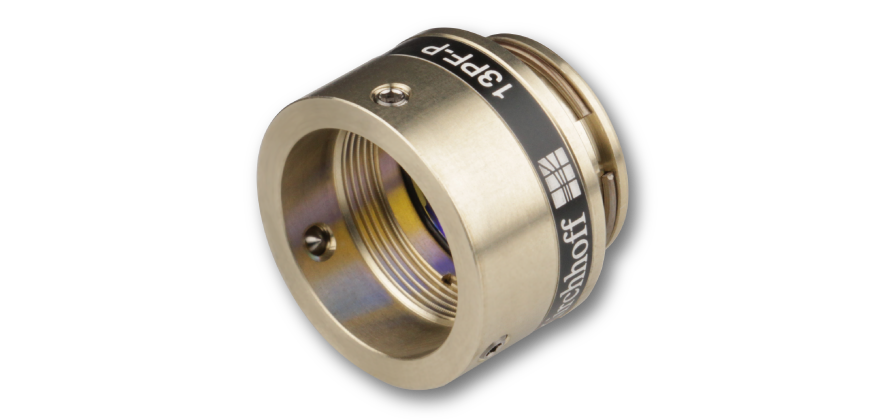
Material
The fiber collimators are made of nickel silver and black anodized aluminum.
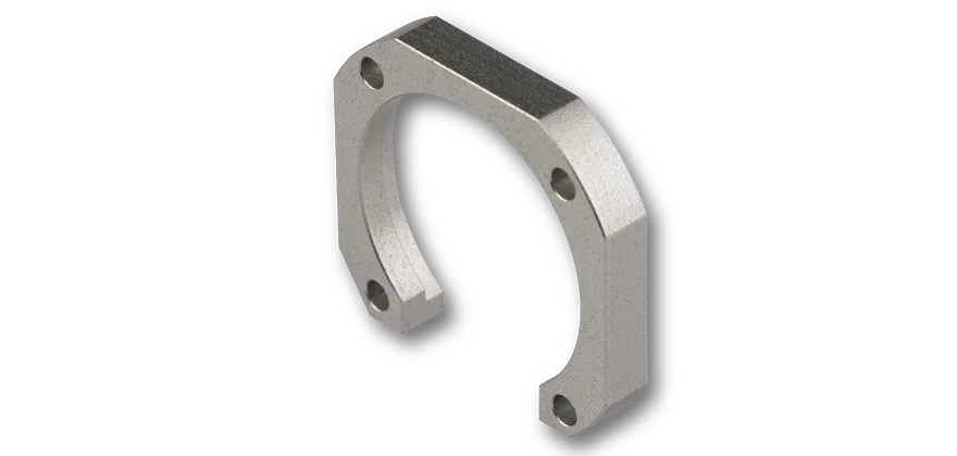
MountingThe mounting options for Fiber Collimators 60FC-L can be found here for
diameter Ø25 mm without flange,
diameter Ø25/28 mm with flange,
diameter Ø32 mm,
diameter Ø45 mm and
diameter Ø55 mm.