Titanium Laser Beam Couplers series 60SMS

for coupling into single-mode and polarization-maintaining fiber cables

Laser beam coupler Titanium 60SMS-1-4
Representative product images. Individual product images are found on the individual product pages.

Features

High precision fiber coupler (fiber port) optimized for high pointing stability and long-term stability. Efficient coupling of ­collimated laser radiation into ­single-mode and PM fiber cables.
  • Made from amagnetic titanium
  • For single-mode or PM fiber cables
  • System mount Ø 19.5 mm
  • Integrated TILT and focusing adjustment
  • Focal lengths up to 18 mm
  • Choice of aspheres, monochromats, achromats and apochromats
  • Various AR coatings for UV - IR
  • Choice of fiber receptacles: FC PC or FC APC (standard), many others available
  • With integrated TILT adjustment
With integrated TILT adjustmentMade from Titanium

Description

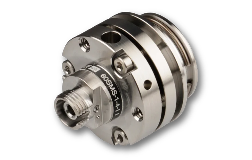
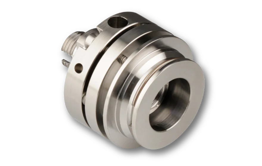
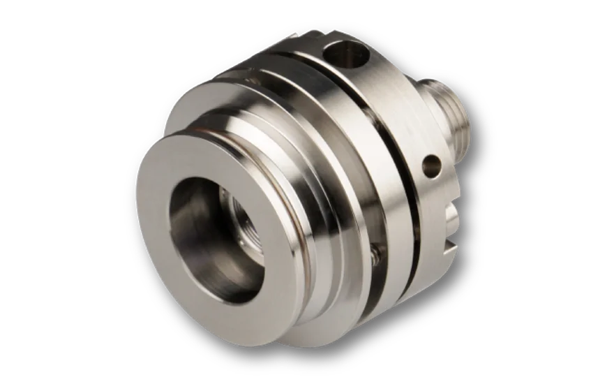
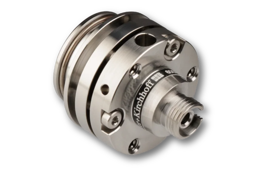
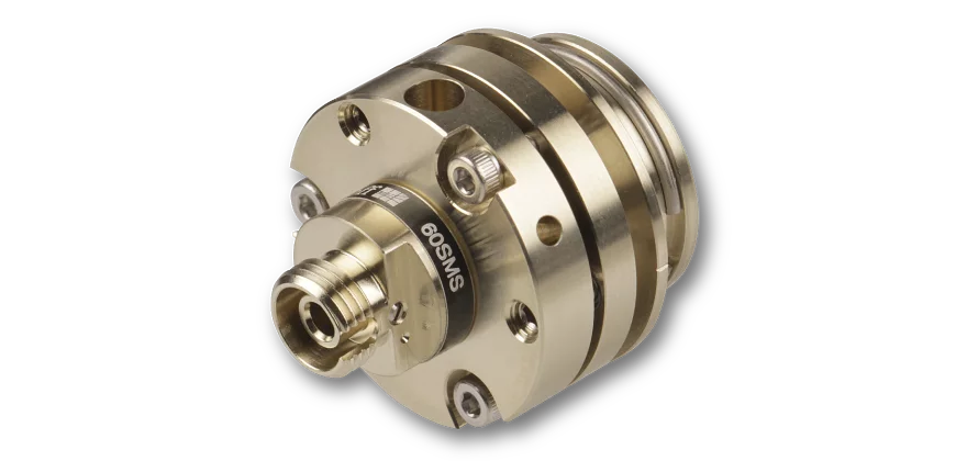
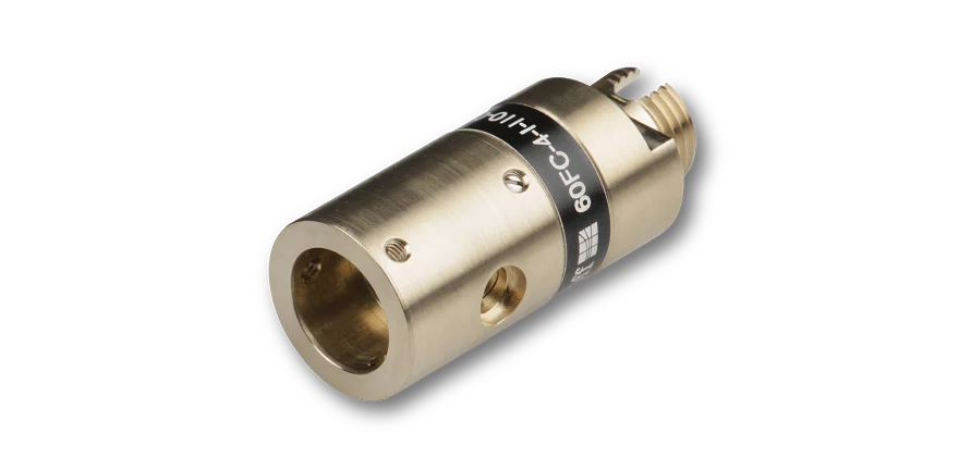
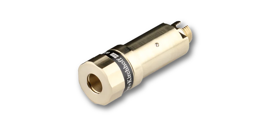
The laser beam couplers series 60SMS made from amagnetic titanium are designed for compact and long-term stable coupling of single-mode laser radiation into a single-mode or polarization-maintaining fiber. For multimode applications please use the series 60FC-A19.5 fiber couplers.

An optics for each application
A large variety of coupling optics allows that the optimum focal length and the best lens type for a single wavelength (asphere, monochromat) or a wavelength range (achromat or apochromat) can be selected for each application. All lenses are AR-coated. For an ideal Gaussian beam and standard fibers you can reach coupling efficiencies up to 80%.

High long-term stability
It‘s compact size as well as the high-resolution alignment mechanisms allow for a straight-forward, intuitive coupling procedure. The result is a fiber coupling with high thermal stability, pointing stability, that is vibration and shock-insensitive. Long-term stability tests (see figure on the right) have shown a power stability better than 3% for a temperature range of 15-35°C.

6* Degrees of freedom
In order to achieve optimum coupling efficiency the fiber coupler needs to provide certain degrees of freedom. You need to adjust

  • the angle between laser beam and lens/fiber end-face
  • the z-position of the lens
  • adjust the polarization axis of the fiber to that of the laser source
  • center the lens with respect to the laser beam

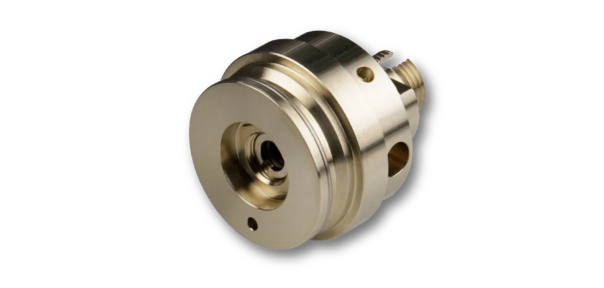
The fiber coupler provides all degrees of freedom necessary. It has a TILT adjustment, an independent focus adjustment, can be rotated 360°, and allows for lateral adjustment* using e.g. the adapter 60A19.5-F.
The TILT adjustment is used to maximize the lateral overlap between the mode field of the fiber and the focussed laser spot using 3 adjustment screws. 3 locking screws are used for fine-adjustment and to lock the position for an optimum mechanical stability.
Independent to the TILT adjustment, the distance between fiber end-face and coupling optics is adjusted by means of an eccentric key. The final focus setting is locked by means of two radially arranged clamping screws. Since the focus adjustment is independent, the z-position of the mode field diameter can be placed much more precisely.
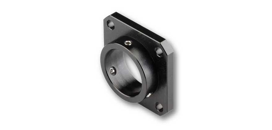
The polarization alignment of the fiber to the polarization axis of the laser source is performed by rotating the laser beam coupler. The separation of the fiber coupler and the adapter necessary for centering is essential to allow for a full 360° freedom of rotation. The coupler has a tight-fit cylinder that can be placed into a Ø 19.5 mm receptacle of a corresponding adapter.
The beam can be centered with respect to the aperture of the coupling optics using e.g. the adapter 60A19.5-F

Optimum lens performance
The angled polish of connectors of type APC causes the beam to exit in an angle and not parallel to the optical axis of the fiber. This is corrected by the pre-angled mechanical coupling axis of the coupler that compensates the beam deflection and you can use the lens centrically. This minimizes aberrations simply resulting from a non-ideal beam path through the lens.

Connector Type options
The fiber coupler can be equipped with receptacles of type FC PC (wide key*), FC APC (wide key*), ST or LSA (compatible with fiber connectors type DIN, AVIO and AVIM). SMA-905 (F-SMA) type receptacles are available for 0° and 5° or 8°-polish e.g. for SMA-905 High Power connectors. In case of FC or LSA with a spring loaded ferrule the fiber coupler has an additional grub screw to increase pointing stability. *Even though the fiber coupler has a wide key receptacle it still can be used with both narrow key and wide key fibers. More information can be found here.

Amagnetic titanium
The fiber couplers are made from amagnetic titanium. The relative permeability of titanium is near 1 (µr=1.00005) making it almost transparent to magnetic fields. The linear coefficient of thermal expansion is close to that of the optics so that a thermal stability over a larger temperature range can be expected.

Long-term stability

FAQ

  • Adjustment
    • How much can I change the focus setting?
      For couplers and collimators with a focal length < 12 mm you can change the focus setting ± 0.5 mm. For couplers and collimators with a focal length ≥ 12 mm you can change the focus setting ± 1.0 mm.
    • I am unsure how to correctly adjust my coupler/collimator. Where do I find details about the adjustment procedure?
      Please refer to the manual in the Downloads section for a detailed adjustment procedure.
    • My collimator is shipped "prealigned". What does this mean?
      Schäfter+ Kirchhoff ships all collimators prealigned and collimated for either a specific wavelength defined by the customer or a typical wavelength. The collimation is performed using professional collimating telescopes.

      Please note: The fibers used in the standard adjustment procedure are all equipped with an end cap when aligning for wavelengths ≤ 520 nm. The adjustment wavelength is given on the label for each collimator/coupler. If a fiber with end cap was used it is marked by "EC".

  • Fiber Receptacle
    • FC PC and FC APC
      • What type of receptacle does my collimator with receptacle type FC have? Narrow key or wide key?
        All our fiber collimators and couplers with a receptacle type FC have a so calles wide key receptacle (2.14 mm).  

        These are suitable for connecting fibers with connector type FC (wide key) but also with thos of type narrow key! You can find the details in the FAQs below.
      • How do I attach a fiber cable?

        1. To prevent damage to the sensitive fiber end-face, always insert the fiber connector`s ferrule at an angle, with the connector key properly aligned to the receptacle notch.
        2. When the ferrule tip is safely located in the inner cylinder of the receptacle, align the connector to the receptacle axis and carefully introduce the connector into the fiber coupler.
        3. Then, orient the connector key in a way that it is pressed gently onto the right-hand side of the receptacle notch ("right-hand orientation rule").
        4. Gently screw on the connector cap nut onto the receptacle until it is finger-tight.
        5. Gently tighten the fiber grub screw to reduce the free play of the ferrule in the receptacle.

      • What is the "right-hand orientation rule"?

        When the ferrule tip is safely located in the inner cylinder of the receptacle, align the connector to the receptacle axis and carefully introduce the connector into the fiber coupler. 

        Then, orient the connector key in a way that it is pressed gently onto the right-hand side of the receptacle notch.

        The tightened grub screw and the "right-hand orientation rule" for the connector, ensure a high reproducibility in mode field position and angle, which is especially important for attaching and reattaching polarization-maintaining fibers reproducibly.

      • Can I attach a narrow key fiber cable to a fiber coupler with a wide key receptacle?

        Yes, you can- without any problem. Simply adhere to the "right-hand orientation rule".

        Generally, with any FC PC or FC APC type connector there is a freeplay when inserting the fiber into the fiber coupler. The free play in between the connector ferrule and receptacle is only a few microns, but necessary for inserting the ferrule without force. There is a difference between the receptable and key width for wide key (2.14 mm) and narrow key (2.0 mm) fibers. If you follow the so-called "right-hand orientation rule" you can reproducibly attach and reattach even PM fibers with narrow key receptacle to fiber couplers with wide key receptacle without difficulty.

        "Right-hand orientation rule":

        When the ferrule tip is safely located in the inner cylinder of the receptacle, align the connector to the receptacle axis and carefully introduce the connector into the fiber coupler. Then, orient the connector key in a way that it is pressed gently onto the right-hand side of the receptacle notch. The tightened grub screw and the "right-hand orientation rule" for the connector, ensure a high reproducibility in mode field position and angle, which is especially important for attaching and reattaching polarization-maintaining fibers reproducibly.


  • Troubleshooting
    • I can‘t collimate the radiation out of a coupler. Why?
      • Have you loosened the grub screws?
        The clamp screws have to be loosened before changing the focus setting, Please refer to the adjustment instructions of the individual couplers for more details.
      • Have you checked, if the fiber is correctly placed within the fiber receptacle of the coupler?
        The fiber connector might not be placed correctly within the receptacle of the coupler/collimator. In particular, please check the small grub screw holding the connector's ferrule (e.g. for FC PC and FC APC type couplers). It might be in the way. Please refer to the adjustment instructions of the individual couplers/collimators for more details.
      • Have you tried another eccentric key?
        Please check, if the eccentric key is damaged or broken.

        Please also check, if you are using the appropriate eccentric key. The eccentric key type 60EX-5 has a larger stroke compared to the key type 60EX-4. The 60EX-5 is used for couplers/collimators with focal length ≥ 12 mm. The 60EX-4 is used for focal lenghts < 12 mm.

        In some very rare cases (e.g.shorter wavelengths and end cap fibers) the stroke of the original eccentric key may be too small for the coupler in your applictation. (See FAQ "Difference between 60EX-4 and 60EX-5"). Try using the 60EX-5 in this case.
      • Have you checked the eccentric key for damage?
        The eccentric key might be damaged or broken. If that is the case, try another eccentric key of the same type and (or) contact Schäfter+Kirchhoff for replacement.
      • Are you using a fiber with an end cap?
        Collimating/coupling with an end cap fiber cable is no different than with a standard fiber cable. However, the focus position might vary a little (<200 µm) when swapping a standard fiber cable for a fiber cable with end cap.

        The eccentric key 60EX-4 is used to adjust the focus position. In some cases the stroke is not large enough.

        This includes working with very small wavelegths or very large wavelengths. Please try using the eccentric key 60EX-5 with a larger stroke instead.

    • It says my coupler/collimator was "precollimated" but the collimation setting seems to not be alright. What might be the problem?
      • Are you using the same wavelength as the adjustment wavelength?
        Schäfter+ Kirchhoff ships all collimators/couplers prealigned and collimated/preadjusted for either a specific wavelength defined by the customer or a typical wavelength. The prealigned is performed using professional collimating telescopes.

        The adjustment wavelength is given on the label for each collimator/coupler. If you are using another wavelength you need to change the focus setting. Please refer to the manual for more details.
      • Are you using the same fiber type as in the adjustment procedure?
        The fibers used in the standard adjustment procedure are all equipped with an end cap when aligning for wavelengths ≤ 520 nm. The adjustment wavelength is given on the label for each collimator/coupler. If a fiber with end cap was used it is marked by "EC".

        If you are not using a fiber with an end cap but the preadjustment at Schäfter+Kirchhoff was done using an end cap ("EC") or you are using a fiber with an end cap and the preadjustment at Schäfter+Kirchhoff was done without, you might need to change the focus setting. Please refer to the manual for more details.

Downloads

Manual
Adjustment_SMS.pdf (Manual)
Technote
Article_SM_FiberCoupling.pdf (Technote)
Technote
Article_FibercouplingNAe2.pdf (Technote)

This downloads section only includes general downloads for the complete series.
Please access the individual product pages (using the product configurator, the product list, order options or the search button if you have a complete order code). Here you will find specific downloads including technical drawings or stepfiles.