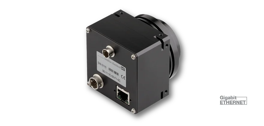
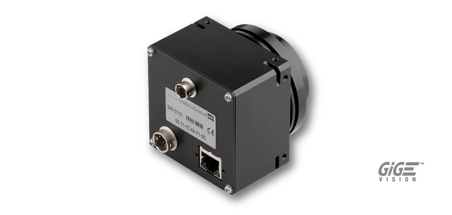
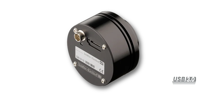
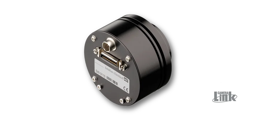
Line scan cameras are semiconductor cameras used in many industrial environments e.g. in machine vision applications. The single photosensitive line sensor contains up to 22800 picture elements (pixels). Light energy incident on the sensor is transformed into an electric signal for digitization within the camera. Color line scan cameras provide three separate line signals for Red, Green and Blue. At 8-bit resolution, the A/D converter transmits the output voltage of each pixel into one of 256 brightness levels for each color line, at 12-bit resolution into 4096 brightness levels. The digitized output signal is transfered to a computer.
The image produced by a line scan camera is one-dimensional and represents the brightness profile of an object,
captured at the current position of the line sensor. A two-dimensional image is generated by performing a scanning movement of either the object or the camera, during which the individual line signals are transferred to the computer and assembled one by one into a 2D image.
When acquiring color images, it must be taken into account that the red, green and blue sensor lines are spatially separated in the sensor and that there
is also a gap between the sensor lines. This results in a working direction of the camera when processing the data. And also the extration of the color values for an image point from different image lines must be considered. The Software Development Kit from Schäfter + Kirchhoff provides convenient functions for this purpose, so that the temporally and spatially correct assignment of colors is guaranteed.
All lenses show some vignetting as a function of the field angle. Hence, even with homogeneous object illumination,
the signal intensity of the image decreases with increasing image height. Shading correction (or flat field compensation) is used to compensate for lens vignetting as well as for inhomogeneity in the illumination. Shading correction is achieved by performing a white balance calibration during illumination of a homogeneous white target. The shading correction procedure is also used for white balance calibrations in color line scan cameras. The different sensitivities of the individual color channels of the sensor are compensa ted for, as well as any color inhomogeneity arising from the illumination source.


