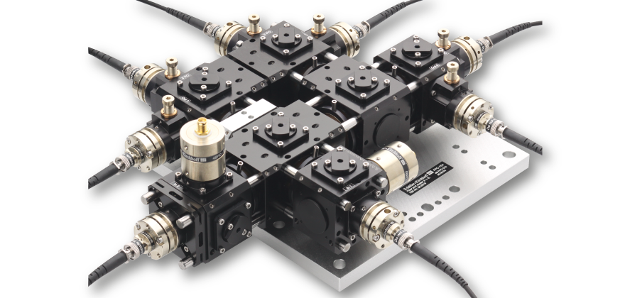
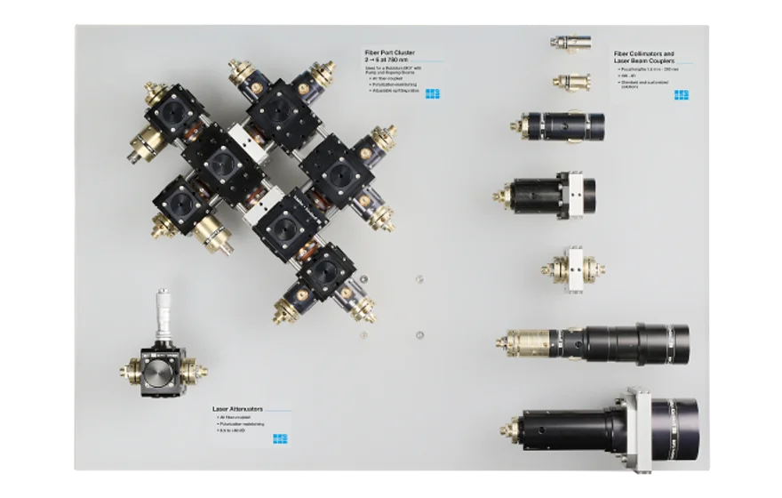
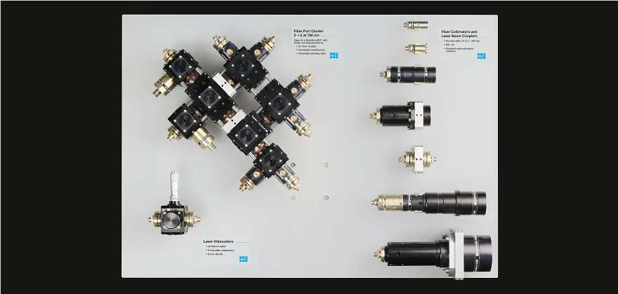
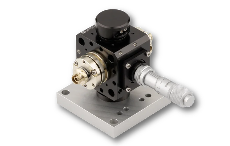
- First setup: Fiber Port Cluster 2 ⇾ 6
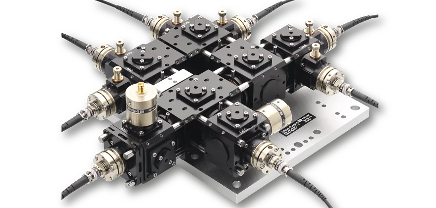
- Second setup: Fiber Collimators and Couplers of different series
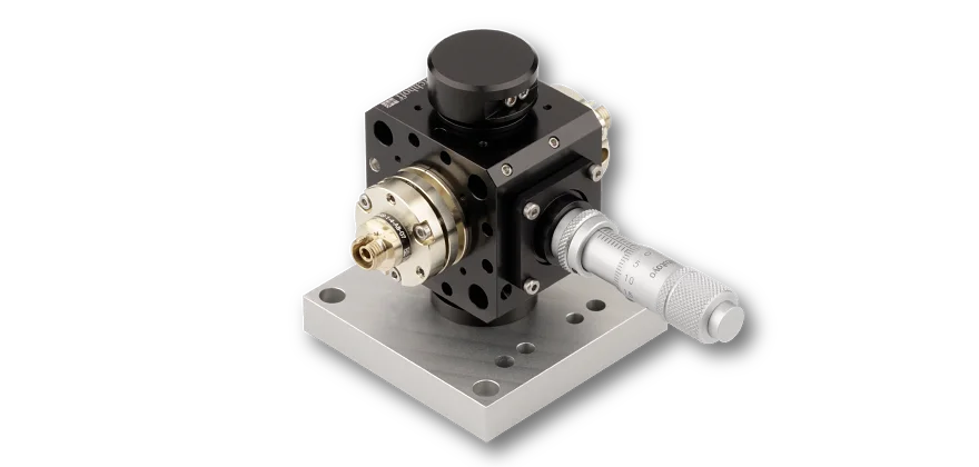
- Third setup: In-line attenuator
More information about the Fiber Port Cluster can be found here.
Exhibition Setup
First Setup: Working principle of the Fiber Port Cluster 2⇾6
The two input ports are fiber coupled to PM fiber cables. Polarizers define the input polarization which is necessary for a long term stable splitting ratio.
Two photo diodes right after each input port allow for a continuous monitoring of the radiation. The two input sources are superimposed by means of a polarization beam splitter.
Subsequently, the radiation splitting is achieved by using a cascade of rotary half-wave plates in combination with polarization beam splitters. By use of the rotary half-wave plates, almost any desired splitting ratio can be achieved.
At the output ports further polarizers are placed in order to define the radiation at output of the system.

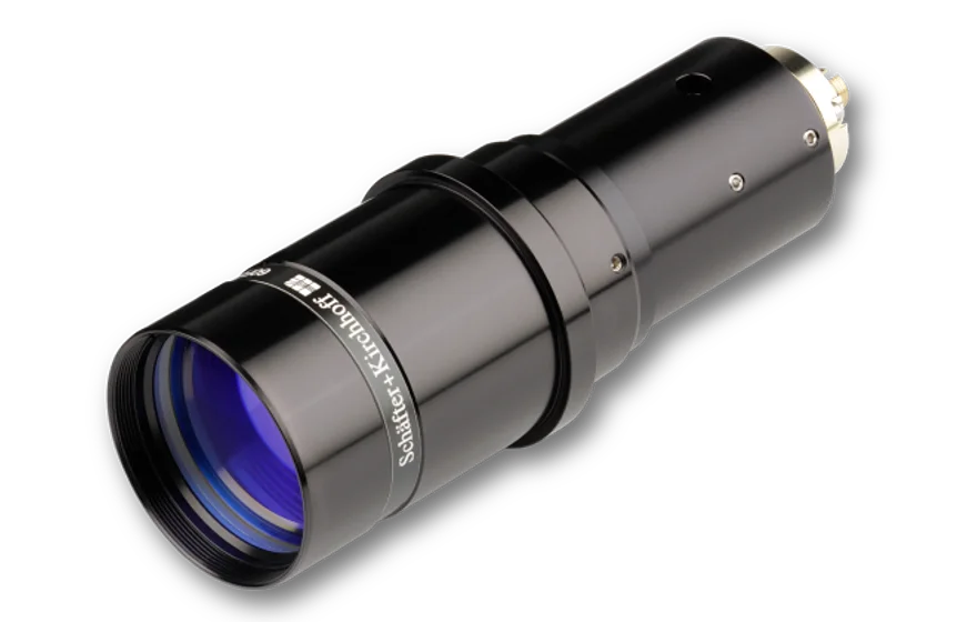
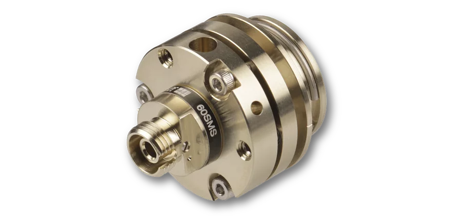
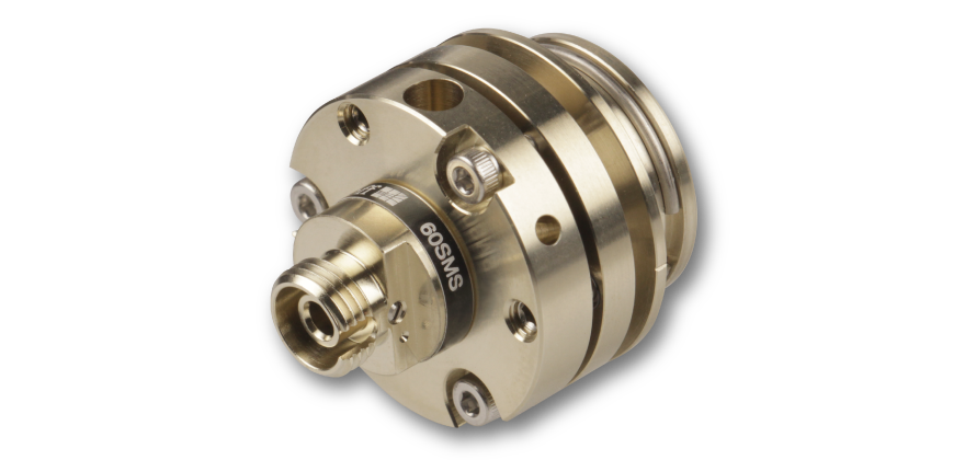
Laser Beam Coupler 60SMS
A fundamental component of the Fiber Port Cluster is the Laser Beam Coupler, which is the input into the opto-mechanical unit collimating the input radiation and, finally, coupling the radiation back into the polarization-maintaining fiber cables. The stability of the total Fiber Port Cluster is determined by the stability of the laser beam coupler.

The setup shows a wide range of fiber collimators including fiber collimators series 60FC, fiber collimators series 60FC-SF with super-fine thread, fiber collimators 60FC-T with integrated TILT adjusment, fiber collimators series 60FC-E with elliptical beam profile and fiber collimators series 60FC-Q with integrated quarter-wave plate. The adequate fiber collimator or fiber coupler can be found using the Fiber Coupler Product Configurator.
Third Setup: In-line attenuator
Compact, rugged and highly efficient opto-mechanical unit for interconnecting two fiber cables. More information can be found here.
for coupling into single-mode and polarization-maintaining fiber cables
All Fiber Couplers and Collimators sorted by series.

Product configurator for all fiber couplers and collimators
| Bit depth | ||||||||||
|---|---|---|---|---|---|---|---|---|---|---|
| SK8k-U3DR4 | 8192 | 3.5 x 3.5 µm | 28.7 mm | 45.4 kHz | X | X | X | USB 3.0 | 8/10 Bit | |
| SK4k-U3DR7C | 4096 x 2 | 7 x 7 µm | 28.7 mm | 45.4 kHz | X | X | X | USB 3.0 | 8 Bit | |
| SK4096MVHW | 4096 | 7 x 200 µm | 28.7 mm | 2.4 kHz | X | X | X | GigE Vision | 8/12 Bit | |
| SK2048MVHW | 2048 | 14 x 200 µm | 28.7 mm | 4.6 kHz | X | X | X | GigE Vision | 8/12 Bit | |
| SK1024U3HA | 1024 | 8 x 8 µm | 8.2 mm | 52.6 kHz | X | X | X | X | USB 3.0 | 8/12 Bit |
| SK1024VJR-4 | 1024 | 14 x 14 µm | 14.3 mm | 4.7 kHz | X | X | GigE Vision | 8/12 Bit | ||
| SK512U3SH | 512 | 14 x 14 µm | 7.2 mm | 35.7 kHz | X | X | X | X | USB 3.0 | 8/12 Bit |
| SK2048VSH-4L | 2048 | 14 x 14 µm | 28.7 mm | 14 kHz | X | X | X | GigE Vision | 8/12 Bit | |
| SK2048MVSH | 2048 | 14 x 14 µm | 28.7 mm | 14.1 kHz | X | X | X | GigE Vision | 8/12 Bit | |
| SK2048CSH | 2048 | 14 x 14 µm | 28.7 mm | 14 kHz | X | X | X | Camera Link | 8/12 Bit | |
| SK1024VSH-4 | 1024 | 14 x 14 µm | 14.3 mm | 27 kHz | X | X | X | GigE Vision | 8/12 Bit | |
| SK1024U3SH | 1024 | 14 x 14 µm | 14.3 mm | 27 kHz | X | X | X | X | USB 3.0 | 8/12 Bit |
| SK1024MVSH | 1024 | 14 x 14 µm | 14.3 mm | 27 kHz | X | X | X | GigE Vision | 8/12 Bit | |
| SK1024CSH | 1024 | 14 x 14 µm | 14.3 mm | 27 kHz | X | X | X | Camera Link | 8/12 Bit | |
| SK7500VTF-4XB | 7496 | 7 x 7 µm | 52.5 mm | 10.1 kHz | X | GigE Vision | 8/12 Bit | |||
| SK7456U3TO | 7456 | 4.7 x 4.7 µm | 35.0 mm | 5.2 kHz | X | X | USB 3.0 | 8/12 Bit | ||
| SK512U3HU | 512 | 25 x 500 µm | 12.8 mm | 26.3 kHz | X | X | X | X | USB 3.0 | 8/12 Bit |
| SK4096U3HW | 4096 | 7 x 200 µm | 28.7 mm | 2.4 kHz | X | X | X | X | USB 3.0 | 8/12 Bit |
| SK22800VJRC-4XC | 7600 x 3 | 9.3 x 9.3 µm | 70.9 mm | 4.9 kHz | GigE Vision | 3*8 Bit | ||||
| SK22800U3JRC-XC | 7600 x 3 | 9.3 x 9.3 µm | 70.9 mm | 6.2 kHz | X | USB 3.0 | 3*8 Bit | |||
| SK22800CJRC-XC | 7600 x 3 | 9.3 x 9.3 µm | 70.9 mm | 6.2 kHz | X | Camera Link | 3*8 Bit | |||
| SK2048VJR-4L | 2048 | 14 x 14 µm | 28.7 mm | 4.7 kHz | X | X | GigE Vision | 8/12 Bit | ||
| SK2048VHA-4 | 2048 | 8 x 8 µm | 16.4 mm | 52.6 kHz | X | X | X | GigE Vision | 8/12 Bit | |
| SK2048U3SH | 2048 | 14 x 14 µm | 28.7 mm | 14 kHz | X | X | X | X | USB 3.0 | 8/12 Bit |
| SK2048U3JR | 2048 | 14 x 14 µm | 28.7 mm | 4.7 kHz | X | X | X | USB 3.0 | 8/12 Bit | |
| SK2048U3HW | 2048 | 14 x 200 µm | 28.7 mm | 6.9 kHz | X | X | X | X | USB 3.0 | 8/12 Bit |
| SK2048U3HU | 2048 | 12.5 x 500 µm | 25.6 mm | 7.1 kHz | X | X | X | X | USB 3.0 | 8/12 Bit |
| SK2048U3HA | 2048 | 8 x 8 µm | 16.4 mm | 52.6 kHz | X | X | X | X | USB 3.0 | 8/12 Bit |
| SK2048CJR | 2048 | 14 x 14 µm | 28.7 mm | 4.7 kHz | X | X | Camera Link | 8/12 Bit | ||
| SK2048CHA | 2048 | 8 x 8 µm | 16.4 mm | 52.6 kHz | X | X | X | Camera Link | 8/12 Bit | |
| SK1024U3HV | 1024 | 25 x 500 µm | 25.6 mm | 13.9 kHz | X | X | X | X | USB 3.0 | 8/12 Bit |
| SK1024U3HU | 1024 | 12.5 x 500 µm | 12.8 mm | 13.9 kHz | X | X | X | X | USB 3.0 | 8/12 Bit |