Fiber Collimator Series 60FC-E-Q

for an ellipical beam cross-section and with a circular state of polarization

60FC-E-4-F30x90
60FC-E-4-F30x90
60FC-E-4-F57x171
60FC-E-4-F57x171
60FC-E-4-F70x210
60FC-E-4-F70x210
Representative product images. Individual product images are found on the individual product pages.

Features

Schäfter+Kirchhoff fiber collimators of series 60FC-E-Q have a collimated elliptical beam with an axis ratio of up to 1:3. These fiber collimators incorporate a quarter-wave plate and generate a circularly polarized beam.
  • Aspect ratio up to 1:3
  • Polarization circularly polarized
  • Gaussian intensity profiles along both elliptical axes
  • Rugged and compact design
  • A front-fitting for attachments, such as a diaphragm
For Fiber Collimators with elliptical collimated beam and linear polarization see series 60FC-E.

Description

In some quantum optical experiments, collimated laser beams with an elliptical cross-section and a circular state of polarization are used, for example as cooling beams in two dimensional magneto-optical traps (2D-MOTs) or in mirror MOTs. They are suitable for polarization-maintaining fiber cables leading to collimated beams with a Gaussian intensity profile and an elliptical beam cross section with an axis ratio of up to 1:3.


An optics for each application
A large variety of optical designs allows that the optimum focal length and the aspect ratio you need can be selected for each application. All lenses are AR-coated.

Optical design
The radiation of the fiber is collimated to a beam with a diameter in the range Ø 1 - 4 mm.
In this collimated beam a low-order quarter-wave plate changes the state of polarization from linear to left-handed or to right-handed circular. An adjacent anamorphic beam shaping optics transforms the circular beam into a beam with an elliptical cross section. Finally the beam is expanded to the desired diameter.

Adjustment of focus
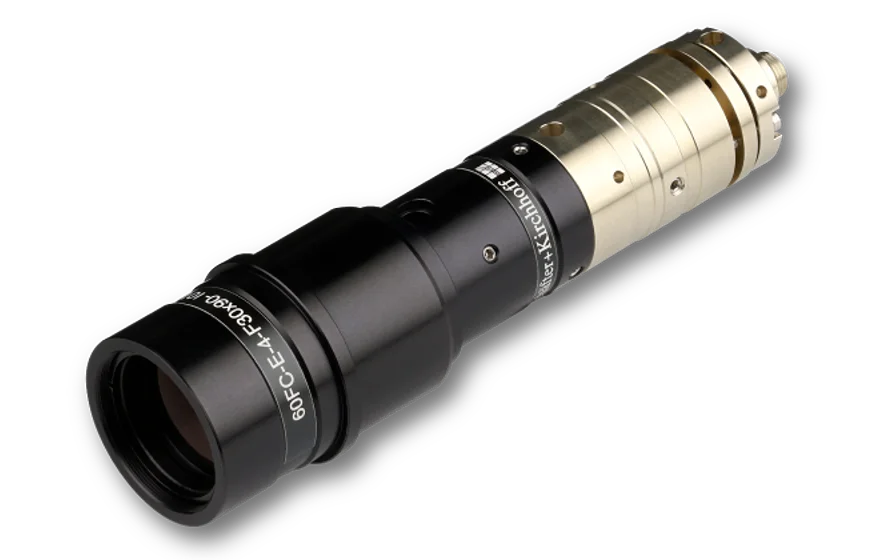
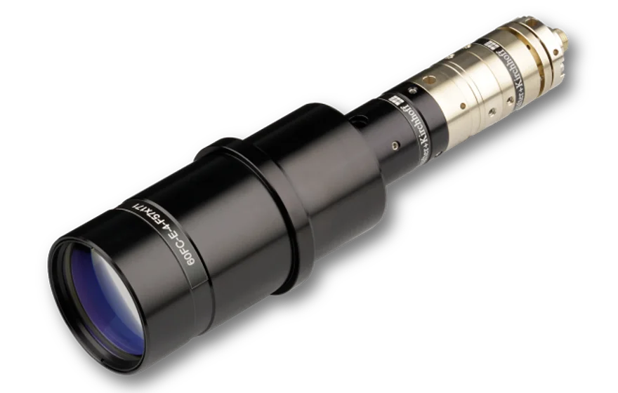
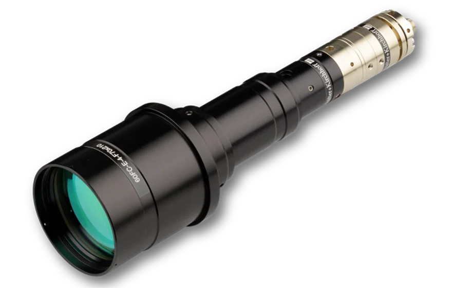
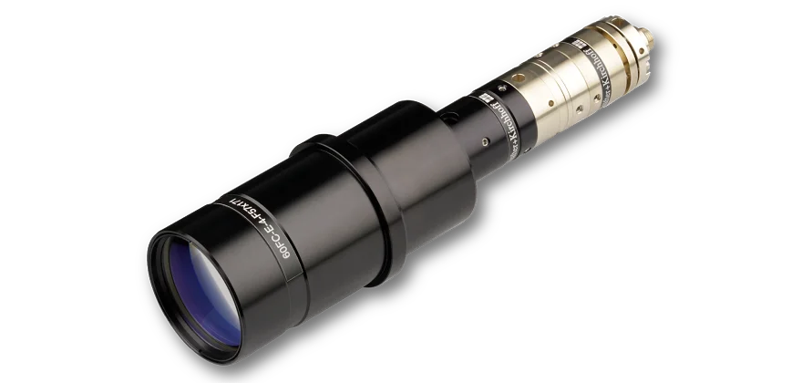
All fiber collimators of seris 60FC-E-Q are aligned for the specified wavelength.
In case of need you can change the distance between fiber end-face and the first collimating optics by means of an eccentric key. The lens does not rotate when adjusting the focus fo both cases. The final focus setting is locked by means of two radially arranged clamping screws. Additionally attachment optics can be mounted to the front of the collimator.

Optimum lens performance
The angled polish of connectors of type APC is considered by a pre-angled mechanical coupling axis that compensates the beam deflection and you can use the lens centrically. This minimizes aberrations simply resulting from a non-ideal beam path through the lens.

Connector Type  
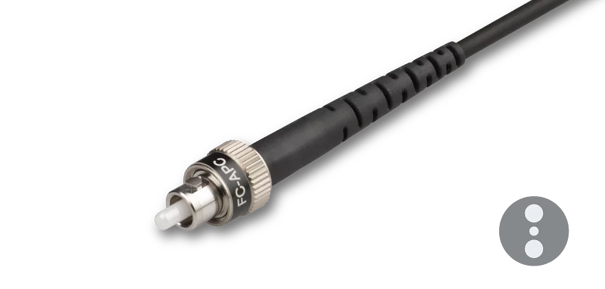
The fiber collimator can be equipped with FC PC (wide key*), FC APC (wide key*), SMA-905 (F-SMA), ST or LSA (compatible with fiber connectors type DIN, AVIO and AVIM) receptacles. In case of FC or LSA with a spring loaded ferrule the fiber coupler has an additional grub screw to increase pointing stability.

Material
The fiber collimators are made of nickel silver and black anodized aluminum.

Mounting
The collimators series 60FC-E-Q all posses a flange for low-strain mounting e.g. using the clamp collars series CC.

Option
Besides these series 60FC-E-Q fiber collimators there is the series 60FC-E. These fiber collimators generate a collimated beam with elliptical cross section and a linear state of polarization.

60FC-E-Q optical scheme

Order Options

Order CodeAspect RatioEff. Focal LengthDesign WavelengthQuarter-Wave PlateClear ApertureFor Connector Type
60FC-E-Q461-4-F30x901 : 330 x   90 mm461nmlow-order20 mmFC APC
60FC-E-Q761-4-F30x901 : 330 x   90 mm741 nmlow-order20 mmFC APC
60FC-E-Q421-4-F30x901 : 330 x   90 mm421 nmlow-order20 mmFC APC
60FC-E-Q671-4-F30x901 : 330 x   90 mm671 nmlow-order20 mmFC APC
60FC-E-Q780-4-F57x1141 : 2 57 x 114 mm780 nmlow-order29 mmFC APC
60FC-E-Q780-4-F57x1711 : 3 57 x 171 mm780 nmlow-order29 mmFC APC
60FC-E-Q780-4-F70x2101 : 3 70 x 210 mm780 nmlow-order48 mmFC APC
60FC-E-Q852-4-F70x2101 : 3 70 x 210 mm852 nmlow-order48 mmFC APC
60FC-E-Q780-4-F90x1801 : 2 90 x 180 mm780 nmlow-order40 mmFC APC

FAQ

  • General Questions
    • Why do you use low-order wave plates for the 60FC-Q collimators instead of zero-order?
      The fiber collimators of series 60FC-Q typically are used in quantum optical systems with narrow line width lasers.
      In these fiber collimators, the quarter-wave plate is placed directly after the fiber receptacle in the diverging beam. 

      Thus, we use low-order waveplates for this application because they have a ten times smaller angular dependence compared to zero-order waveplates.

      It may be better to use zero-order plates only if the parts are used in a non-temperature-stabilized environment or if they are used with a broadband source.

      Series 60FC-Q fiber collimators with zero-order plates are available upon request.

  • Fiber Receptacle
    • FC PC and FC APC
      • What type of receptacle does my collimator with receptacle type FC have? Narrow key or wide key?
        All our fiber collimators and couplers with a receptacle type FC have a so calles wide key receptacle (2.14 mm).  

        These are suitable for connecting fibers with connector type FC (wide key) but also with thos of type narrow key! You can find the details in the FAQs below.
      • How do I attach a fiber cable?

        1. To prevent damage to the sensitive fiber end-face, always insert the fiber connector`s ferrule at an angle, with the connector key properly aligned to the receptacle notch.
        2. When the ferrule tip is safely located in the inner cylinder of the receptacle, align the connector to the receptacle axis and carefully introduce the connector into the fiber coupler.
        3. Then, orient the connector key in a way that it is pressed gently onto the right-hand side of the receptacle notch ("right-hand orientation rule").
        4. Gently screw on the connector cap nut onto the receptacle until it is finger-tight.
        5. Gently tighten the fiber grub screw to reduce the free play of the ferrule in the receptacle.

      • What is the "right-hand orientation rule"?

        When the ferrule tip is safely located in the inner cylinder of the receptacle, align the connector to the receptacle axis and carefully introduce the connector into the fiber coupler. 

        Then, orient the connector key in a way that it is pressed gently onto the right-hand side of the receptacle notch.

        The tightened grub screw and the "right-hand orientation rule" for the connector, ensure a high reproducibility in mode field position and angle, which is especially important for attaching and reattaching polarization-maintaining fibers reproducibly.

      • Can I attach a narrow key fiber cable to a fiber coupler with a wide key receptacle?

        Yes, you can- without any problem. Simply adhere to the "right-hand orientation rule".

        Generally, with any FC PC or FC APC type connector there is a freeplay when inserting the fiber into the fiber coupler. The free play in between the connector ferrule and receptacle is only a few microns, but necessary for inserting the ferrule without force. There is a difference between the receptable and key width for wide key (2.14 mm) and narrow key (2.0 mm) fibers. If you follow the so-called "right-hand orientation rule" you can reproducibly attach and reattach even PM fibers with narrow key receptacle to fiber couplers with wide key receptacle without difficulty.

        "Right-hand orientation rule":

        When the ferrule tip is safely located in the inner cylinder of the receptacle, align the connector to the receptacle axis and carefully introduce the connector into the fiber coupler. Then, orient the connector key in a way that it is pressed gently onto the right-hand side of the receptacle notch. The tightened grub screw and the "right-hand orientation rule" for the connector, ensure a high reproducibility in mode field position and angle, which is especially important for attaching and reattaching polarization-maintaining fibers reproducibly.


  • Troubleshooting
    • I can‘t collimate the radiation out of a coupler. Why?
      • Have you loosened the grub screws?
        The clamp screws have to be loosened before changing the focus setting, Please refer to the adjustment instructions of the individual couplers for more details.
      • Have you checked, if the fiber is correctly placed within the fiber receptacle of the coupler?
        The fiber connector might not be placed correctly within the receptacle of the coupler/collimator. In particular, please check the small grub screw holding the connector's ferrule (e.g. for FC PC and FC APC type couplers). It might be in the way. Please refer to the adjustment instructions of the individual couplers/collimators for more details.
      • Have you tried another eccentric key?
        Please check, if the eccentric key is damaged or broken.

        Please also check, if you are using the appropriate eccentric key. The eccentric key type 60EX-5 has a larger stroke compared to the key type 60EX-4. The 60EX-5 is used for couplers/collimators with focal length ≥ 12 mm. The 60EX-4 is used for focal lenghts < 12 mm.

        In some very rare cases (e.g.shorter wavelengths and end cap fibers) the stroke of the original eccentric key may be too small for the coupler in your applictation. (See FAQ "Difference between 60EX-4 and 60EX-5"). Try using the 60EX-5 in this case.
      • Have you checked the eccentric key for damage?
        The eccentric key might be damaged or broken. If that is the case, try another eccentric key of the same type and (or) contact Schäfter+Kirchhoff for replacement.
      • Are you using a fiber with an end cap?
        Collimating/coupling with an end cap fiber cable is no different than with a standard fiber cable. However, the focus position might vary a little (<200 µm) when swapping a standard fiber cable for a fiber cable with end cap.

        The eccentric key 60EX-4 is used to adjust the focus position. In some cases the stroke is not large enough.

        This includes working with very small wavelegths or very large wavelengths. Please try using the eccentric key 60EX-5 with a larger stroke instead.

    • It says my coupler/collimator was "precollimated" but the collimation setting seems to not be alright. What might be the problem?
      • Are you using the same wavelength as the adjustment wavelength?
        Schäfter+ Kirchhoff ships all collimators/couplers prealigned and collimated/preadjusted for either a specific wavelength defined by the customer or a typical wavelength. The prealigned is performed using professional collimating telescopes.

        The adjustment wavelength is given on the label for each collimator/coupler. If you are using another wavelength you need to change the focus setting. Please refer to the manual for more details.
      • Are you using the same fiber type as in the adjustment procedure?
        The fibers used in the standard adjustment procedure are all equipped with an end cap when aligning for wavelengths ≤ 520 nm. The adjustment wavelength is given on the label for each collimator/coupler. If a fiber with end cap was used it is marked by "EC".

        If you are not using a fiber with an end cap but the preadjustment at Schäfter+Kirchhoff was done using an end cap ("EC") or you are using a fiber with an end cap and the preadjustment at Schäfter+Kirchhoff was done without, you might need to change the focus setting. Please refer to the manual for more details.

Downloads

Technote
Article_FiberCollimators.pdf (Technote)

This downloads section only includes general downloads for the complete series.
Please access the individual product pages (using the product configurator, the product list, order options or the search button if you have a complete order code). Here you will find specific downloads including technical drawings or stepfiles.