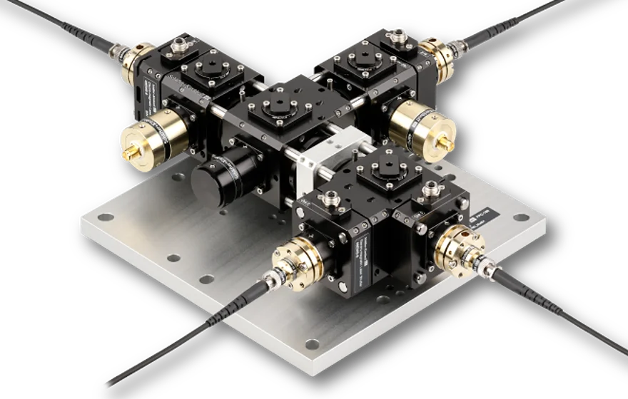
48-FPC-2-2_dc-xxx_Mod01

Fiber Port Cluster 2 ⇾ 2 dichroic, with shutters

Fiber Port Cluster 2-2 dc Mod01

Features

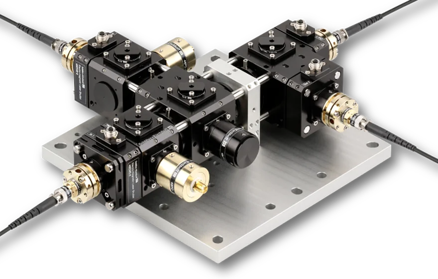
Fiber Port Cluster for one input source
  • Configuration 2 ⇾ 2 dc
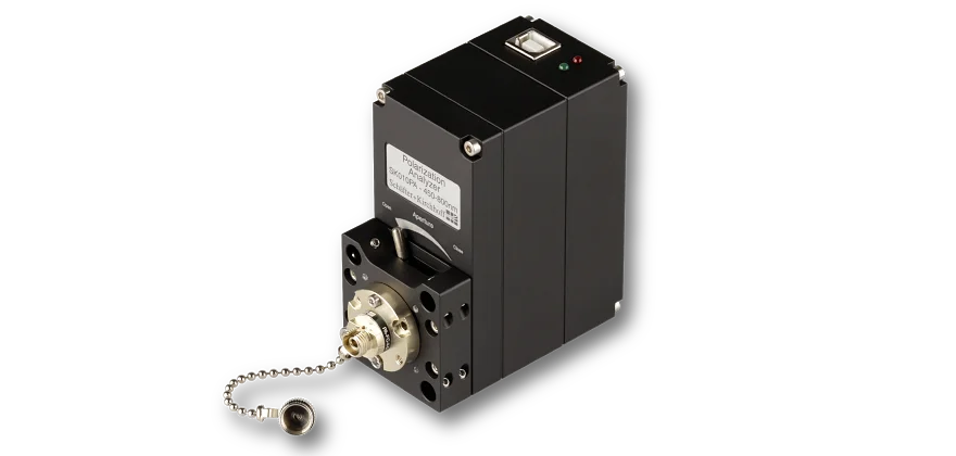
  • Electro-magnetic shutters at the two input ports
  • Electro-magnetic shutters at the two output ports
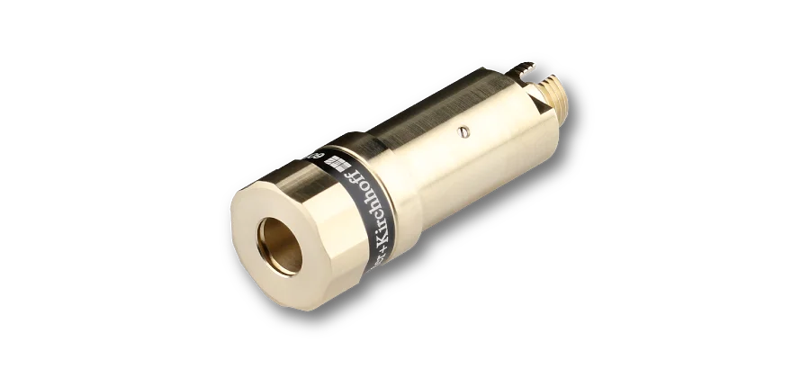
  • Highly efficient coupling into polarization-maintaining fiber cables
  • Adjustable splitting ratio
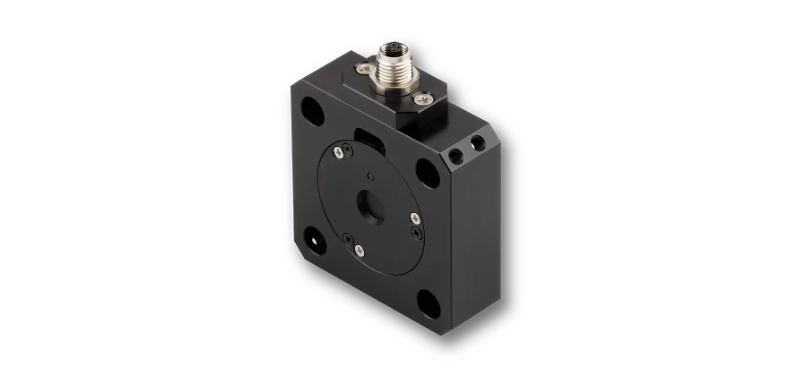
  • Compact, rugged, transportable and sealed opto-mechanical units
  • Fully fiber-coupled
  • Very high long-term stability, efficiency and reproducability

Description

This Fiber Port Clusters2 ⇾ 2 dc Mod01 is a compact opto-mechanical unit that combines two fiber-coupled sources with differing wavelengths and then splits the combined radiation into 2 output fiber cables with high efficiency and variable splitting ratio. Electro-magnetic shutter is placed at each of the two input ports and output ports.

Optical Setup
The input port is fiber-coupled to a PM fiber cable. A polarizer defines the input polarization which is necessary for a long term stable splitting ratio.
A photo diode right after the input port allows for a continuous monitoring of the radiation.
Subsequently, the radiation splitting is achieved by using a rotary half-wave plate in combination with a polarization beam splitter. By use of the rotary half-wave plate, almost any desired splitting ratio can be achieved.
At the output ports further polarizers are placed in order to define the polarization at output of the system.

Fiber Couplers
A fundamental component of a Fiber Port Cluster is the Laser Beam Coupler, which is the input into the opto-mechanical unit collimating the input radiation and, finally, couples the radiation back into the polarization-maintaining fiber cables. The stability of the total Fiber Port Cluster is determined by the stability of the laser beam coupler.

Electro-magnetic Shutters
An electro-magnetic shutter is placed at each of the two input ports and output ports. For a description and further technical specifications, please refer to the electro-magnetic shutter type 48EMS-6.

How to order
For a detailed quotation please additionally specify

  • Wavelengths In 1 and In 2
  • Cable lengths
  • Connector types
48-FPC-2-2_dc

Technical data

48-FPC-2-2_dc-xxx_Mod01

Order code
48-FPC-2-2_dc-xxx_Mod01
Configuration
2 ⇾ 2 dc
 
electro-magnetic shutters
Wavelengths*
767 + 780 nm
Fiber type
polarization-maintaining
Connector type
FC APC (standard)
Cable lengths
customer-specific
Wave plate type
low-order
Power monitor
BPX-61 (SMA)
Transmission
≥ 70 % @ 767 nm
≥ 60 % @ 780 nm
Polarization Extinction Ratio
≥ 23 dB @ 767 + 780 nm
Balancing
better 3 %
* Different wavelength combinations on request

Downloads

Dimensional drawing
980129090615.pdf (Dimensional drawing)
STEP model
980129090615.stp (STEP model)
STEP model
980129090615.stp (STEP model, for registered users only)
Manual
48-FPC-2-2_dc_Mod01_Example.pdf (Manual)
Manual
48-FPC-2-2_dc_Mod01_Example.pdf (Manual, for registered users only)
Technote
Article_Cluster.pdf (Technote)

Benefits of user registration include

  • Extended information for download including stepfiles, software or manuals
  • Direct download of user-specific downloads (e.g. user-specific software)
  • Access to previous online requests and the possibility to add complete previous lists to the "Request for quote" list
  • Stored item list
Click here to register.