
Characterizing Polarization-maintaining Fibers (PM Fibers)
Real PM fiber cables
Ideally, Polarization-maintaining fiber cables maintain the linear state of polarization (SOP) of light that is coupled into the fiber. However, in reality, these polarization-maintaining fiber cables can influence the polarization state to a small extent. As a result, the light emerging from the cable is slightly elliptically polarized.
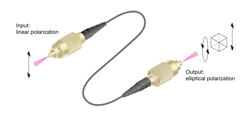
Schematic drawing of a polarization-maintaining fiber cable. Due to the termination of the fiber connector, the polarization state at the cable exit may generally be slightly elliptical.
Definition of Extinction ratio V and PER
The preservation of linear SOPs in polarization-maintaining fiber cables is characterized by an extinction ratio E. This is the fraction of linearly polarized light coupled into the fiber, that is transmitted by a polarizer (analyzer) at the cable end, Pp, versus the fraction Ps blocked by the polarizer.
{!{!{E=\frac{P_p}{P_s}.}!}!}The extinction ratio E is typically expressed as the logarithmic polarization extinction ratio PER:
{!{!{PER=10\ \cdot logE}!}!}The extinction ratio is a measure for the ellipticity η of the light, and it is:
{!{!{E=\cot^2(\eta)}!}!}
Poincaré representation
SOPs can be visualized on the Poincaré sphere, as it is done with the Polarization Analyzer series SK010PA,and as you can see in the figure below. In this representation, linear SOPs are located on the equator of the sphere, and circularly polarized states are located at the two poles. Please note that the handedness of the polarization is defined here from the perspective opposite to the direction of propagation. When facing a circularly polarized beam the polarization is right-handed if the electric field vector rotates clockwise, and left-handed if the rotation is counter-clockwise. The expected polarization states at the output of a polarization-maintaining fiber cable may deviate slightly from the equator. The angle of inclination in this representation is the ellipticity η. More information on PM fiber coupling using the Polarization Analyzer can be found here or in an article here.
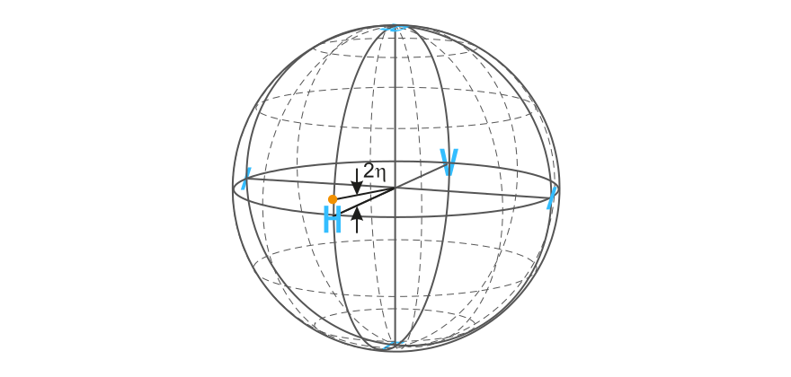
Poincaré sphere and definition of ellipticity
Poincaré sphere for the representation of arbitrary polarization states. Here, a slightly elliptical polarization state is depicted, as it can occur e.g at the output of a PM fiber cable.
Mean and varying ellipticity
The polarization maintenance of a polarization-maintaining fiber cable is characterized by the ellipticity η. The fiber itself typically has a good polarization maintenance. With this assumption, the ellipticity is affected by the cable ends only, which means that disturbances occur at the terminated connectors of the fiber cable (or at the in- and outcouplers). The ellipticity η consists of two parts, which appear differently in the polarization measurement and which can have different effects when using the fiber cables.
{!{!{\ \eta(t)=\bar{\eta}+\Delta\eta(t)\\ }!}!}
The first component, the mean ellipticity {!{\bar{\eta}}!} , can be caused by disturbances (e.g. stress birefringence) at the outcoupling end.
The second component, Δη, arises when there is a mismatch between the polarization axis of the radiation and the fibers principal axes at the incoupling end. The light is then split between the two fiber axes. Due to a non-constant group delay difference in the two main polarization axes of the fiber, the components coupled into the two polarization axes experience a temporally changing path difference. This path difference can be affected by temperature changes or by bending the fiber. The light exiting the fiber cable then has an arbitrary elliptical SOP.
Assuming that the coherence length of the laser source is large enough, the varying component of the ellipticity Δη can be visualized on the Poincaré sphere and consists of measurement points lying on a circle around the stable ellipticity state {!{\bar{\eta}}!} .
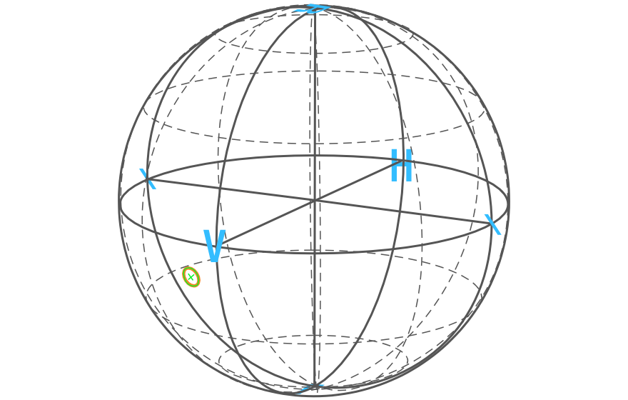
Poincaré plot of an elliptical SOP exiting a PM fiber cable
Poincaré plot of the polarization state at the output of a PM fiber cable. Due to fluctuations (e.g. thermal), the polarization state moves on a circle on the Poincaré sphere. The polarization is quite stable over time, but clearly elliptical (the complete circle lies below the equator).
Definition of minimum PER
The worst possible SOP is represented by the point on the circle that is most distant from the equator. It is reached when the azimuth and elevation angles on the Poincaré sphere are added directly {!{\eta=|\bar{\eta}|+\Delta\eta,}!} .At this point, the polarization extinction ratio is the lowest of all the points on the circle. Therefore, this point leads to the minimum PER of the current measurement.
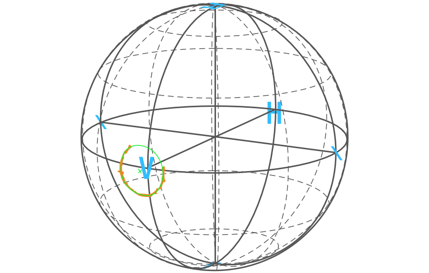
Good mean PER but large ellipticity
The center of the circle lies close to the equator, indicating a good mean PER. There are two points that cross the equator, where the SOP is linear, but these states are generally not stable.
Reverse measurement
Examining a fiber cable in the opposite direction (swapping the fiber input to become the fiber output, and vice versa) also switches the two components of the ellipticity.
A measurement circle with a small radius, {!{\ \Delta\eta_a}!} and its center {!{\bar{\eta}_a}!},far from the equator, see below on the left, becomes a large circle with radius, {!{\Delta\eta_b}!} and center {!{\bar{\eta}_b}!}, close to the equator (see below on the right). Therefore, the minimum extinction ratio, calculated from the direct sum of {!{\bar{\eta}}!} and {!{\Delta\eta}!}, is the same for both measurements, not taking into consideration measurement errors.