The Polarization Analyzer can also be used to set a well-defined state of polarization for free-beam applications. For this type of measurement, it is essential to align the laser beam axis correctly with the polarization analyzer. The beam must be entering the device perpendicular to its front face. This can be done using the microbench, or 40 mm cage system and using the connection with 4 rods or the rail system.
Polarization Alignment: coupling into polarization-maintaining fibers

The SK010PA Polarization Analyzer provides procedures for aligning the incoming polarization direction of the laser source with the polarization axes of the fibers, and for the measuring the resulting Polarization Extinction Ratio (PER).
Polarization-maintaining single-mode fibers guide coupled radiation in two perpendicular principal states: the fiber polarization axes (also called the slow and fast axis, see the figure on the left). Further information on how Schäfter+Kirchhoff characterizes PM fibers can be found here.

The polarization extinction ratio PER of fiber-coupled radiation is the ratio of the optical power levels coupled to the two polarization axes of the fiber. The Polarization Analyzer can be used to match the polarization axis of the light source to that of the fiber by adjusting the polarization of the source until it aligns with the polarization axes of the fiber, see figure on the left.
For the two polarization axes the speeds of propagation are different due to the fiber’s birefringence. When linearly polarized radiation is not coupled exactly into one of these states, it is split into two perpendicular components that are coupled to both polarization axes of the fiber. At the fiber exit, the difference in propagation speed causes a phase shift which also depends on the length of the fiber. If this phase shift is smaller than the coherence length of the laser source, the radiation recombines to form an elliptically polarized state.
Conversely, if the coherence length of the laser source is smaller than the phase shift the emerging radiation is partly depolarized. The Polarization Analyzer supports adjustment for both cases.
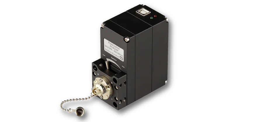
The Polarization Analyzer SK010PA
More information about technical details can be found on the product page.

Adjustment using the Poincaré sphere
If the phase shift causes the radiation to recombine into an elliptical state, an evaluation using the Poincaré sphere can be used.
The difference in propagation speed and the resulting phase shift of the two fiber axes depend on temperature and stress. Consequently, the polarization at the fiber output is not stable when there is an alignment mismatch. The polarization changes when the fiber is touched and fluctuates with temperature variations. However, the exit polarization is not random. When mapped onto the Poincaré sphere, all possible exit states are found to lie on a common circle.
The radius of this circle indicates the quality of the alignment, since it shows the angle deviation between the fiber polarization axis and the polarization axis of the incoming radiation. For an optimally aligned ideal fiber, the data circle converges to a single point: the center of the circle. Generally, this center represents the mean polarization state of the particular alignment. For an ideal PM-fiber, it is located on the equator of the Poincaré sphere.
This correspondence between circle radius and polarization alignment is used in the Polarization Analyzer’s fiber alignment procedure.
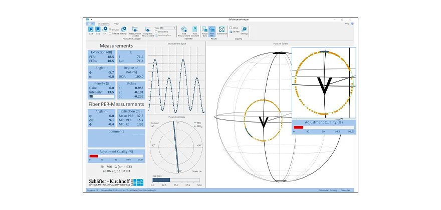
Step 1 Measurement of the initial alignment
The procedure begins with the recording of the exit polarization states while the temperature is changed or the fiber is carefully bent to cause the exit polarization to fluctuate. A circle is then automatically fitted to the data points and the mean and minimum PER values are displayed. In the example shown, the circle on the Poincaré sphere has a large radius.
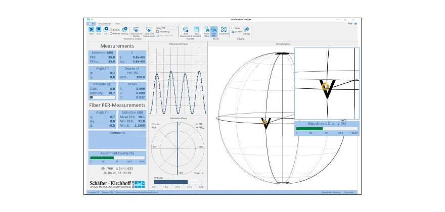
Step 2 Real-time adjustment with feedback and final measurement of the optimized alignment
During continuous measurement of the exit polarization state, the polarization axis of the laser source is rotated relative to the fiber axis (or vice versa). Optimum alignment is reached when the exit polarization state is as close as possible to the circle center on the Poincaré sphere. A color-coded logarithmic bar plot helps to find the minimum distance.
A second measurement then reveals the parameters of the optimized polarization alignment of the fiber.
Adjustment with DOP Ellipse
If the coherence length of the laser source is smaller than the phase shift caused by the difference in propagation speed, the light becomes partially depolarized and adjustments can be made using the DOP ellipse.

As mentioned above, recombination to an elliptical polarization state is only possible, if the coherence length of the laser source is greater than the phase shift caused by the difference in propagation speed. If the coherence length of the laser source is smaller, then the light is partially depolarized and no recombination occurs.
The described circle on the Poincaré sphere cannot be observed - all exit polarization states lie at a single point. Instead, the misalignment solely results in a reduced degree of polarization (DOP).
In this case, the DOP-ellipse representation can be used for fiber alignment, where a polarization measurement with a ¬rotating linear polarizer is simulated. The DOP-ellipse (dotted line) becomes a circle for fully depolarized light.
The narrower the DOP-ellipse becomes, the better the incoming polarization axis is aligned to one of the -polarization axes of the fiber. For an ideal alignment, the ellipse collapses to a line. In this case, since the polarization axis is aligned with the principal fiber axis, no depolarization occurs as the light is not split into two components with different propagation speeds. Therefore, the linear SOP remains intact regardless of the coherence length.
Free Beam Measurements
Adjustment and Quantification of Quarter-Wave Plates

The SK010PA Polarization Analyzer can be used to align and quantify retardation optics, e.g. fiber collimators with integrated quarter-wave plates series 60FC-Q.
The polarization that is launched from these collimators is adjusted by rotating the quarter-wave plate using a special tool. One full rotation traces out a figure-of-eight on the Poincaré sphere. Circularly polarized light is achieved when the poles are reached, with right-handed circular polarization located at the north pole, and left-handed polarization located at the south pole. If the actual retardation of the optics differs from the desired value, the extreme values will not ¬reach the poles. The Polarization Analyzer thus provides a measure of the actual retardation of the optics