Start // Support // Technotes // Technotes - Fiber Optics // Fiber Coupling and Collimation // Stability and coupling efficiency of the laser beam coupler 60SMS

Stability and coupling efficiency of the laser beam couplers type 60SMS

Stability of the laser beam couplers type 60SMS

The high stability of fiber-coupling using a laser beam coupler is demonstrated in temperature-stability tests using different focal lengths and wavelengths. 

The tests show a maximum deviation with respect to the maximum power of 3%.

Long-term stability

Test Set-up

Test setup for measuring the stability of two laser beam couplers (f = 4.5 mm, λ = 405 nm) during successive temperature cycling ­between 15 °C and 35 °C.

The light emitted by the temperature-stabilized laser diode beam ­source 48TE (with integrated Faraday isolator FI) is guided to the test setup using a polarization-maintaining fiber, collimated by a laser beam coupler, and then coupled back into a polarization-maintaining fiber using a second laser beam coupler, that is placed 12 mm apart.

In order to minimize any temperature impact on the ­measurement equipment, the laser source as well as the ­photo detector and the data logger are all placed on a thermo-controlled plate at a constant temperature of 25 °C.

Fiber-to-fiber coupler 60FF-T

Stability of the laser beam coupler and of the fiber-fiber coupler

The experiment described above not only demonstrates the stability of a single laser beam coupler, but also the stability of the fiber-fiber coupler 60FF-T as it is exactly the setup that is tested. 

Long-term stability

Relative Power over time

The recoupled power is monitored using a photo detector. The coupling setup is placed on a thermo-controlled plate, to vary the temperature between 15 °C and 35 °C in successive cycles with a rate of 0.5 °C per minute. The temperature of the coupling system is monitored by a temperature sensor placed on one of the two laser beam couplers.
The figure shows the typical results of the relative transmitted ­power over 5 measurement cycles using a focal length of 4.5 mm and a wavelength of 405 nm. The power is ­normalized with respect to the maximum power acquired over all ­measurement cycles. 

The power deviation from the mean power is ±1.5 %. 

Long-term stability

Relative power over temperature

The repetitive pattern in the relative power caused by the temperature cycling is demonstrated more clearly in the figure on the left, in which the relative power (normalized to the maximum) is plotted against the temperature of the laser beam couplers. 

In this case the maximum coupling efficiency is reached a little above 25 °C and it decreases faster towards lower ­temperatures than higher temperatures, with the smallest slope near the requested operating point (25 °C). 

The respective power curves for each measurement cycle are almost coincident and the power variation at points with equal temperatures is <1 %, which demonstrates the reproducibility of the pointing stability during temperature cycling and the long-term stability of the fiber-coupling. 


The maximum deviation with respect to the maximum power here is 3 %.

How incorrect adjustment affects coupling efficiency

When coupling into single-mode fibers, the Laser Beam Couplers should produce a diffraction-limited spot that matches the mode field diameter and the numerical aperture of the fiber. It is only when this condition is met, that fiber coupling with high coupling efficiencies of up to 85% are achieved.
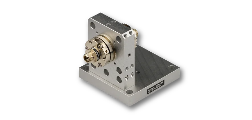
The precision adjustment mechanism is used for the precise lateral alignment of the mode field of the fiber to the focused laser spot in order to achieve maximum overlap. For polarization-maintaining fibers, the polarization axis of the fiber additionally needs to be aligned with the polarization axis of the incoming radiation.
The adjustment is done in four steps:
  • Center the Laser Beam Coupler series 60SMS with the laser beam propagation axis by using the adapter 60A19.5-F (or similar).
  • Move the mode field of the fiber laterally for maximum overlap with the laser spot using the TILT adjustment .
  • Adjust the pre-adjustment of the focus setting (only needed if the wavelength is different than specified).
  • Rotate the Laser Beam Coupler to align the polarization axes (only for PM-fibers).
An in-depth description of the coupling procedure using the Laser Beam Coupler series 60SMS can be found in the manual.

Effects of Decentering on the coupling efficiency

A beam displaced laterally from the optical axis causes it to be focused onto the fiber center, but with ­inclined propagation in relation to the fiber optical axis and parts of the beam exceed the acceptance angle of the fiber.
The inclined propagation causes lens aberrations such as coma and astigmatism to ­appear. These are removed by centering the axes of the laser beam and the coupling optics.

Centering the lens

Incorrect centering: Inclined focusing into the fiber

Schematic drawing of inclined focusing into the fiber due to a decentration of the entrance beam.

Centering coupling loss

Effect of beam decentration on the coupling efficiency

Relative coupling efficiency for lenses with f' 5-15 mm depending on the entrance beam decentration.

Only a coarse alignment of the entrance beam centration is necessary, and this can be done by hand, as the positioning accuracy must only be within 7 - 10 % of the beam diameter.

Effects of lateral displacement on the coupling efficiency

Lateral displacement of the laser beam focus away from the mode field of the fiber arises because of:
  • Production tolerances in the centering of the coupling lens and/or the centering of the fiber core in the fiber ferrule. With a mode field or spot diameter of 2 – 5 µm, the ­required precision is in the sub-micron range
  • Inclined beam propaga­tion
By using the TILT mechanism of the Laser Beam Coupler, the mode field of the fiber is adjusted laterally to achieve overlap with the laser focus spot.
Lateral displacement

Lateral displacement due to non-centered lens or fiber core

Schematic drawing of the lateral displacement

Lateral displacement coupling loss

Effects of lateral displacement on the coupling efficiency

Relative coupling efficiencies for laser spots late­rally displaced from the fiber mode field.

Lateral displacement

Lateral displacement due to inclined beam propagation

Scheamtic drawing of the inclined beam propagation and the resulting lateral displacement.

Lateral displacement coupling loss

Lateral displacement due to inclined beam propagation: Effects on coupling efficiency

Realtive coupling efficiency for inclined beam propagation.
Example: When using a 5 mm focal length lens, a beam inclined by 1 mrad results in a lateral offset of 5 µm, completely missing the mode field and resulting in a very low coupling efficiency.

Effects of defocusing on the coupling efficiency

Schäfter + Kirchhoff Laser Beam Couplers are supplied pre-adjusted for the specified wavelength and refocusing is not necessary for a properly collimated ­laser beam. However for different wavelengths it might be necessary to readjust the focus.

Refocusing fiber scheme

Correct focusing of the Laser Beam Coupler

Schematic drawing of the optimum focus setting

Refocusing fiber scheme

Defocused Laser Beam Coupler

Schematic drawing of a defocused Laser Beam Coupler.

Refocusing coupling loss

Effects of defocusing on the coupling efficiency

Relative coupling efficiency depending on the focus position of the defocused lens.

The positioning accuracy of the laser focus in the coaxial direction is less critical than for the lateral directions. Because of the small depth of focus (Rayleigh range) of the laser spot, however, a decrease in coupling efficiency occurs even with a defocus of only a few microns.  

Correct polarization alignment

Polarization-maintaining single-mode fibers guide radiation in two principle states of polarization (the fast and slow axis). The linear polarization of light coupled into one of the axes is maintained. If light is guided partly in the other axis, then the outcome polarization is elliptical (if the cohe­rence length of the source is larger than the phase difference). Strain and temperature variations, however, change this arbitrary elliptical ­state.

A linear and stable state of polarization is obtained by rotating the Laser Beam Coupler to adjust the axes. This is done precisely with the help of the SK010PA pola­riza­tion analyzer. The analyzer evaluates the polarization extinction ratio and immediately displays the results of any adjustments made to the polarization axis.
The polarization extinction ratio PER, the ratio between the powers guided in the two polarization axes, serves as a decisive measure of the fiber alignment. 
Axis orientation of a PM fiber

Rotated polarization axis

Schematic drawing of the laser polarization axis rotated to the polarization axis of the fiber. 

For a high polarization extinction ration (good polarization alignment) the laser polarization axis needs to be aligned to the slow axis of the fiber.

Angular deviation coupling loss

Effect of misaligned axis on the Polarization extinction ratio

Effect of an angular deviation between the laser and fiber polarization axes on the polarization extinction ratio (PER).